Click the Selection and Smart Drawing Tool button on the toolbar.
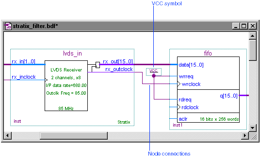
Click the pinstub of the lvds_clock input pin to define the start of the node, and then drag the pointer to draw a line that connects to the rx_inclock input port of the lvds_in symbol.
Repeat step 2 to make the additional node connections between the symbols shown in the following table:
| Make Node Connection From: | To: |
rx_outclock output port of lvds_in symbol |
wrclk input clock port of fifo symbol |
Input pinstub of VCC symbol |
wrreq input port of fifo symbol |
Input pinstub of VCC symbol |
rdreq input port of fifo symbol |

Choose Save (File menu).