Click the Selection and Smart Drawing Tool button on the toolbar.
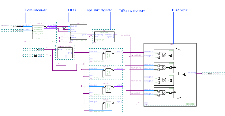
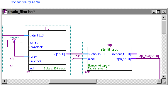
Draw a node line from the fifo
symbol's rdclock input into an empty space.
With the Selection and Smart Drawing Tool, select the node line that is connected to the rdclock clock input port of the fifo symbol.
Choose Properties (right button pop-up menu). The General tab of the Node Properties dialog box appears automatically.
In the Name box, type clk as the name of the node.
Click OK. The signal clk is added to the node, and the name appears above the node line.
Repeat steps 1 through 6 to draw and name the nodes shown in the following table:
| Draw Node From: | To: | Name Node: |
aclr input port of fifo symbol |
Empty space | clr |
clock input port of tap symbol |
Empty space | clk |
clk0 input port of of mac symbol |
Empty space | clk |
Choose Save (File menu). The stratix_filter design is complete.