If necessary, click the Selection and Smart Drawing Tool button ![]() on the toolbar.
on the toolbar.
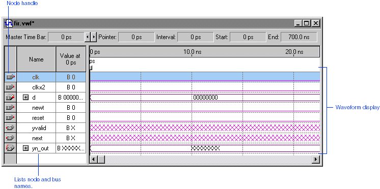
To select the entire clk input node waveform, click the Selection and Smart Drawing Tool on the "handle" of the clk node. The entire node, including the waveform, is highlighted.

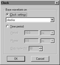
Choose Value > Clock (Edit menu). The Clock dialog box appears.
Under Base waveform on, select Clock settings and select clocka in the list.

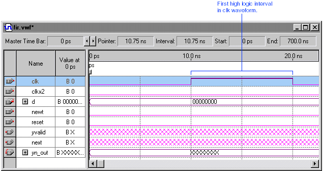
Click OK. The clk waveform is created according to the clocka clock settings.

