Section 3: Create LogicLock Regions
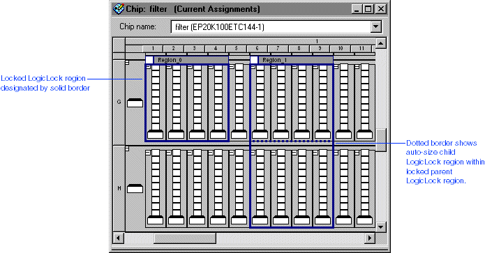
A LogicLock region is a type of placement constraint. You can define any arbitrary rectangular region of physical resources on the target device as a LogicLock region. You can create LogicLock regions in either the Timing Closure or Current Assignments floorplan, or in the LogicLock Regions window. By assigning nodes or entities to a LogicLock region, you direct the Compiler to place those nodes or entities inside the region during fitting. The LogicLock regions you create are displayed in the floorplan. All LogicLock regions are defined by two parameters: size and state. You can define the following three types of LogicLock regions:
LogicLock Region Type:
|
Description: |
| Fixed size, locked state |
The region is defined as a specific height and width. Location is assigned to specific device resource. Locked state regions are designated by a solid border in the floorplan. |
| Fixed size, floating state |
The region is defined as a specific height and width. The Quartus II software chooses the most appropriate location for the region. Floating state regions are designated by a dashed border in the floorplan. |
| Auto-size, floating state |
The Quartus II software determines the optimum size and location for the region. Auto-size regions are designated by a dotted border in the floorplan. |
LogicLock regions can be nested hierarchically. Making one LogicLock region the child of another LogicLock region places the child region inside its parent region and specifies that the child's location is relative to the parent location. When you move a parent region, its child regions maintain their placement relative to the parent region.
 |
Nested LogicLock regions can only be created with the LogicLock Regions window.
|
Show Me

