With the Selection and Smart Drawing Tool, select the node that connects the state_m block to the D input of the DFF primitive.
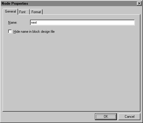
Choose Properties (right button pop-up menu). The General tab of the Node Properties dialog box appears automatically.
In the Name box, type next as the name of the node.

Click OK. The signal next is added automatically to the node, and the name appears above the node line. Adding this name creates a logical connection between the state_m block and the D input of the DFF primitive.
Follow steps 1 through 4 to name the node that feeds the Clock input of the DFF primitive. Name the node clk, so that you can create a logical connection, or a "connection by name," from the INPUT pin clk to the Clock input of the DFF primitive.
Choose Save (File menu).