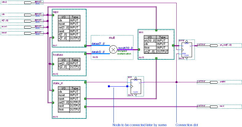
Click the Orthogonal Node Tool button ![]() on the toolbar.
on the toolbar.
Draw a node line from the D input of the DFF symbol
to the border of the state_m block.
Repeat steps 1 through 2 to make the additional node connections shown in the following table:
| Draw Node From: | To: |
D input of the DFF symbol |
border of the state_m block (already entered) |
Q output of DFF primitive |
OUTPUT pin yvalid |
INPUT pin clkx2 |
clock input of the DFFE primitive |
enable (ENA) input of the DFFE
primitive |
Node connecting the Q output of the DFF
primitive to the OUTPUT pin yvalid |
To create a node that can be connected by name, draw a line from the DFF
symbol's clock input into an empty space. You can learn how to complete this node's
connection by name later in this tutorial module.
Choose Save (File menu).