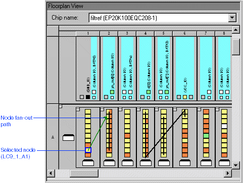
Choose Routing > Show Node Fan-Out (View menu).
Select any one of the used logic cells in the floorplan. By default, the the fan-out is shown in green. The arrows in the fan-out lines indicate the direction of the signal flow.

To display the routing delays, choose Routing > Show Routing Delays (View menu). The routing delays associated with the selected logic cell appear in the floorplan alongside the fan-in and fan-out paths.
When you are finished viewing the fan-in and fan-out paths, turn off Routing > Show Node Fan-Out (View menu).