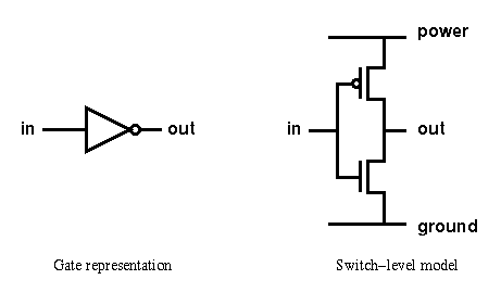
This section provides two examples of implementing circuit designs at switch-level.

The switch-level description has a similar structure to that of the behavioural, functional or gate level codes, as in this example of a CMOS inverter:
// Switch-level description of a CMOS inverter

module inv_sw (out, in);

   output  out;               // inverter output
   input   in;                // inverter input

   supply1 power;             // "power" connected to Vdd
   supply0 ground;            // "ground" connected to Gnd

   pmos (out, power, in);     // instantiate pmos switch
   nmos (out, ground, in);    // instantiate nmos switch

endmodule
Connection to the Vdd power supply is made using the supply1 net, declared as "power". Similarly, the "ground" terminal is connected to the supply0 net.
Using the pmos and nmos switch-level primitives the respective transistors are instantiated, based on the terminology shown in the previous section. Note that the instance name is optional, and has been omitted in this example.

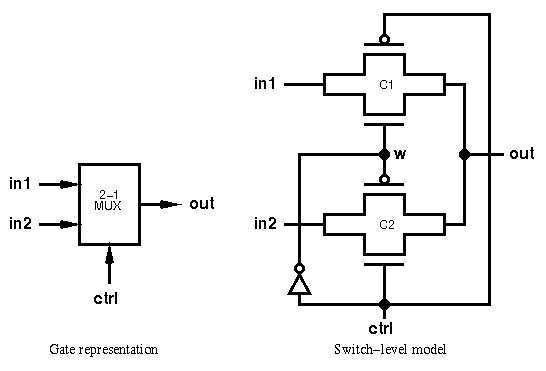
This circuit assigns the output out to either inputs in1 or in2 depending on the low or high values of ctrl respectively.
// Switch-level description of a 1-bit 2-1 multiplexer
// ctrl=0, out=in1; ctrl=1, out=in2

module mux21_sw (out, ctrl, in1, in2);

   output out;                    // mux output
   input  ctrl, in1, in2;         // mux inputs
   wire	  w;                      // internal wire

   inv_sw I1 (w, ctrl);           // instantiate inverter module

   cmos C1 (out, in1, w, ctrl);   // instantiate cmos switches
   cmos C2 (out, in2, ctrl, w);

endmodule
An inverter is required in the multiplexer circuit, which is instantiated from the previously defined module.
Two transmission gates, of instance names C1 and C2, are implemented with the cmos statement, in the format cmos [instancename]([output],[input],[nmosgate],[pmosgate]). Again, the instance name is optional.
Prepared by: Chun Hsiung Ng Last updated: 23 January 1997