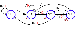
Figure 1: State diagram, describing the sequence detector implemented
as a Mealy machine.
The number in italics underneath the states indicate which part of
the sequence the state remembers.
Finite State Machine implemented as a Mealy Machine:
a non-resetting sequence recognizer
The following state diagram (Fig. 1) describes a finite state machine
with one input X and one output Z. The FSM asserts its output Z when it
recognizes the following input bit sequence: "1011". The machine will keep
checking for the proper bit sequence and does not reset to the initial
state after it has recognized the string. As an example the input string
X= "..1011011..." will cause the output to go high twice: Z = "..0001001.."
. When the machine is in the state S3 the output will go high after the
arrival of a "1" at the input. Thus the output is associated with the transitions
as indicated on the state diagram.

Figure 1: State diagram, describing the sequence detector implemented
as a Mealy machine.
The number in italics underneath the states indicate which part of
the sequence the state remembers.
This state diagram can be described in ABEL code given in Listing 1. The output is described with the "With" keyword to indicate that the output will change when the input goes to one.
Listing 1: ABEL source code for the Mealy Machine implementation of the sequence detector described in Fig. 1
Declarations
"Input and
output signals
X, CLOCK, RST
PIN;
Z PIN istype
'com';
Q1, Q0 PIN
istype 'reg';
"State register
definitions
" and assignments
of state values
SREG = [Q1,Q0];
S0 = [0,0];
S1 = [0,1];
S2 = [1,0];
S3 = [1,1];
Equations
"Define the
clock signal for the state machine
[Q1,Q0].AR
= RST;
[Q1,Q0].CLK
=CLOCK;
"Define state diagram
STATE_DIAGRAM SREG
STATE S0: IF
X THEN S1 ELSE S0;
STATE S1:
IF X THEN S1 ELSE S2;
STATE S2:
IF X THEN S3 ELSE S0;
STATE S3:
IF X THEN S1 WITH Z=1; ELSE S2;
end Seqdet1

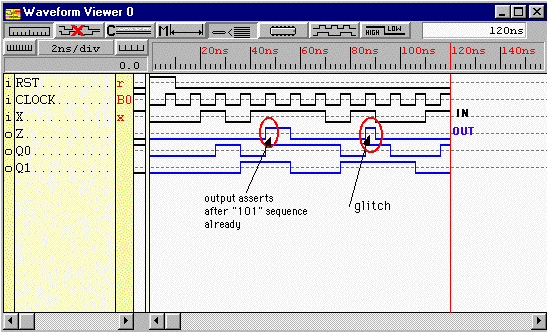
Figure 2: Simulation of the sequence detector for "1011" described with
the state diagram of Fig. 1.
(Screen clip from Xilinx XACTstep(TM) Foundation software)
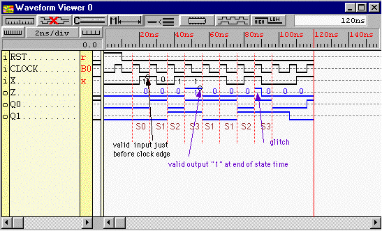
Notice that the output Z asserts as soon as the input is "1" when in state S3. Comparing this output with the one obtained for a Moore machine of the same sequence detector may let a casual observer think that there is a timing problem as the output seems to asserts already after the "101" input sequence. However, when one looks at the output carefully one concludes that the waveform is correct. One has to realize that the outputs are valid at the end of the state time (just before the positive clock-edge) while the valid inputs are sampled just before the positive clock edge as indicated in Figure 3 below. The input sequence "1011" gives indeed an output sequence of "0001".

Figure 3: Output waveform of the Mealy machine (sequence detector for
"1011") with valid inputs and outputs indicated.
(Screen clip from Xilinx XACTstep(TM) Foundation software)
One notices that there is a glitch in the output after the input sequence 10111010. However this occurs at a moment that the output is not valid (the output is valid just before the positive clock edge). The valid output sequence is than 000100000 as expected.
This example indicates that one has to be very careful with the timing when using a Mealy machine. Outputs can show glitches and are only valid at the end of a state time (i.e. just before the the positive clock edge for a positive edge triggered flip-flop or just before the negative clock transition for a negative egde triggered flip-flop). On the other hand a Mealy machine can often be implemented with fewer states that a Moore machine as can be seen from the Moore example. An alternative way to prevent glitches and to make the ouput of a Mealy machine synchronous with the clock, it to use a synchronous Mealy machine. The implementation of the sequence detector as a synchronous Mealy machine is given in the next example.