
Note that the second instruction is fetched from location '0x00000110'; the instruction is '0x20001008'. This corresponds to 'add r1,r0, #8' which is the instruction at the '_main' label in the 'acid_test.s' file.
This lab features a VHDL model for the DLX single cycle implementation discussed in class.
You will be provided with an incomplete model for the DLX single cycle implementation; the lab
assignment involves completing the model so that a target program is executed correctly.
We will use the Mentor Quick VHDL environment to compile/execute/debug the model.
% cat vhdl.tar.Z.sim1 | zcat | tar xf -This will create a directory tree that looks like:
   vhdl/
        /src -- all VHDL source files under
          /dlxsimple   -- VHDL files for single cycle implementation
          /Makefiles   -- Makefiles to compile VHDL files
          /dw01        -- support library
          /utils       -- support library

       /obj  -- all VHDL compiled object code under this tree
You will be editing files in the 'vhdl/src/dlxsimple' directory; you will be
invoking the VHDL simulator from the 'vhdl/src' directory.
Modify your .cshrc file and add the lines
swsetup mgc
set path (~reese/bin $path)
Log off, then log back on and do:
which qhsim
which dlx2obj.branch
This should return pathnames to the 'qhsim' (VHDL simulation) and 'dlx2obj.branch' (utility script) programs.
The files in the 'vhdl/src/dlxsimple' directory implement the single cycle implementation. The most important files are:
make -f Makefiles/Makefile.dlxsimple TOOLSET=qhdlfrom the 'vhdl/src' directory. This Makefile will recompile any files that have been edited and will compile any files that depend on the changed files.
dlx2obj.branch acid_test.sThis will produce a new file called 'acid_test.obj'. The 'acid_test.obj' file should already be present; if you modify 'acid_test.s' for some reason then you will need to rerun 'dlx2obj.branch'. It is important that the entry point of your assembly language program be labeled as '_main'. One of the actions which 'dlx2obj.branch' does is place a:
beqz r0, _mainat location '0' in the instruction memory (it is placed at location '0' because the program counter value is set to '0' on simulator startup). This causes an unconditional jump to the location defined by the '_main' label in your assembly program. This also means that the FIRST dlx instruction that will be executed by the VHDL model is the 'beqz' instruction -- this is the first instruction that you have to get working correctly.
To start up the VHDL simulator, change to the 'vhdl/src' directory and do:
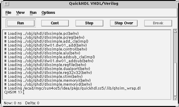
qhsim -lib ../obj/qhdl/dlxsimple cfg_acid_testYou should see the main 'qhsim' window pop up; it is labeled QuickHDL VHDL/Verilog.
view *This will cause MANY windows to pop up; do not be intimidated by the number of windows. The windows and their functions are as follows:
We will need to display some signals in the 'wave' window. I have prepared a command file to add signals to this window; the file is called 'wave.do' and is in the 'vhdl/src' directory. To execute this command file, type:
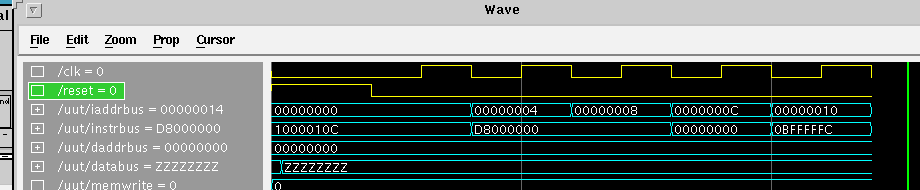
do wave.doin the main simulation window. Click on the 'wave' window and see what signals got added. You should recognize many of the signals as being named very similarly to the signals described in the textbook for the dlx single cycle implementation. You will also note that current register values are also displayed in the 'wave' window. To run the simulation for a period of time, type:
run 600 nsThe clock cycle length is set at 100 ns; this causes the simulation to run for 6 clock cycles. Examining the simulation window reveals what instruction is initially fetched, and how that instruction is executed:
If you fix 'control.vhd' so that the 'bnez' is executed correctly, then the correct simulation
should look like:
Note that the second instruction is fetched from location '0x00000110'; the instruction is
'0x20001008'. This corresponds to 'add r1,r0, #8' which is the instruction at the '_main' label
in the 'acid_test.s' file.
All of the traces in the waveform window are important, the ones you will probably watch the most are:
If the simulation is running, and you change the 'control.vhd' file and recompile, then you
can load in the changed object file by executing 'File->Load New Design' from the main
simulation window (you do not have to exit the simulator).
If you just want to restart the current simulation from time zero,
use the 'File->Restart' menu choice.

You can also set a breakpoint and single step through your
'control.vhd' code by clicking in the 'structure' window on the
'control' component:

This will cause the control code to appear in the source window. Scroll down through the code and click on the source line where you want the breakpoint to occur. The next 'run' command will cause the breakpoint to be hit; the 'Step Over' button can be used to step through the code. The 'variables' and 'signals' windows will display the current variable/signal values. To remove the breakpoint, click on the source line with the breakpoint and it will be removed.
Type 'quit' in the main simulation window to exit the simulation.
The simulation is due on Tuesday, February 4th, at class time. You MUST demo your
simulation to me and convince me that it is correct. Hand in a printout your
final 'control.vhd' file.
If your simulation runs correctly for 'acid_test.s', then the opcodes, alu opcodes, register
values should sequence like:

