For Printing Purposes Only! |
|
Click the Print icon to print this Module. Click the Done or Previous button when finished. |
Simulation Module |
Simulation allows you to test a design thoroughly to ensure that it responds correctly in every possible situation before you program or configure a device.
You must supply input vectors as the stimuli for the Quartus II Simulator. The Simulator uses these input vectors to simulate the output signals that a programmed device would produce under the same conditions. In a typical simulation session, you create multiple sets of input vectors and check the resulting outputs.
Depending on the type of information you need, you can perform functional or timing simulation with the Simulator. Functional simulation tests only the logical operation of a design, while timing simulation tests both the logical operation and the worst-case timing for the design in the target device. The Simulation tutorial module guides you through the steps necessary to create a Vector Waveform File (.vwf), specify Simulator settings, run a timing simulation, and analyze the simulation results.
|
If you have not already sequentially completed the Design Entry, Compilation, and Timing Analysis tutorial modules, you must first open and compile the simulation project before you can begin working in the Simulation tutorial module.
To open the simulation project, follow these steps:
Choose Open Project (File menu). The Open Project dialog box appears.
In the \qdesigns\fir_filter\simulate subdirectory, select the Altera-provided simulate_fir_filter.quartus project file in the Files list.
Click Open.
Choose Start Compilation (Processing menu).
When you receive a message indicating that compilation was successful, click OK.
|
You can create Vector Waveform Files (.vwf) with the Quartus II Waveform Editor to use as stimuli for simulation. VWFs describe the simulation input vectors and simulation outputs as graphical waveforms. You can also specify vector stimuli in a text-based Vector File (.vec). The Quartus II software allows you to open vector source files either in text or waveform format.
| If you are already familiar with creating VWFs with the Quartus II Waveform Editor, you can reduce the time required to complete this tutorial by following the instructions in Copying the Altera-provided Vector Waveform File, rather than creating the file from scratch. |
|
To create a VWF, follow these steps:
Choose New (File menu). The New dialog box appears.
To select VWF as the file type, click the Other Files tab and select Vector Waveform File.
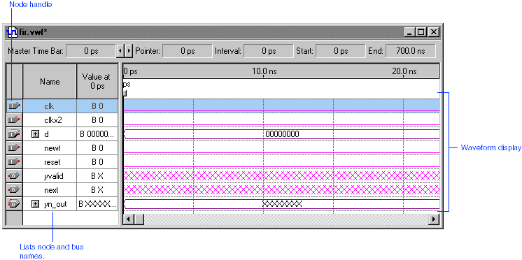
Click OK. The Waveform Editor opens, displaying an empty waveform file.
![]()
To change the end time for the file, choose End Time (Edit menu).
In the Time box, type 700 and select ns in the list.
Click OK.
To save the file as fir.vwf, choose Save As (File menu). The Save As dialog box appears.
In the Save in list, select the fir_filter directory.
In the File name box, type fir.
Click Save.
|
You can complete the VWF by entering the input node waveforms and the desired output node waveforms.
To add the input and output nodes, follow these steps:
To find the node names you want to add to the file, choose Utility Windows > Node Finder (View menu). The Node Finder appears.
In the Node Finder, select Pins: all in the Filter list.
To find the nodes you want to add to the VWF, click Start.
![]()
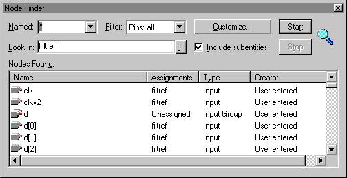
In the Nodes Found list, select the clk, clkx2, d, newt, reset, yvalid, next, and yn_out pins and drag them into the Name column of the VWF. You can select multiple contiguous names with Shift+Click or select multiple non-contiguous names with Ctrl+Click.
Close the Node Finder.
| You can also create custom filters for finding nodes in the design with the Node Finder. You can go to "Creating a Custom Filter" in Quartus II Help for specific instructions about creating a custom filter. | |
|
You create the input vectors for simulation by specifying the logic levels of the node waveforms. The logic level changes represent the behavior of signals in the design.
To edit the clk input node waveform, follow these steps:
If necessary, click the Selection and Smart Drawing Tool button ![]() on the toolbar.
on the toolbar.
To select the entire clk input node waveform, click the Selection and Smart Drawing Tool on the "handle" of the clk node. The entire node, including the waveform, is highlighted.
![]()
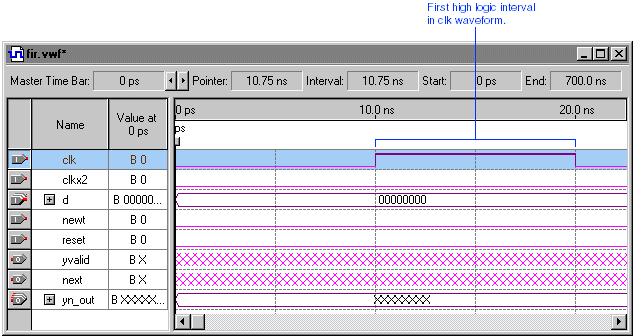
Choose Value > Clock (Edit menu). The Clock dialog box appears.
Under Base waveform on, select Clock settings and select clocka in the list.

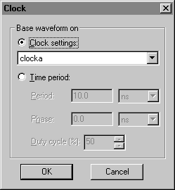
Click OK. The clk waveform is created according to the clocka clock settings.
![]()
|
To edit the clkx2 input node waveform, follow these steps:
Click the Selection and Smart Drawing Tool button on the toolbar.
To select the entire clkx2 input node waveform, click the Selection and Smart Drawing Tool on the "handle" of the clkx2 node. The entire node, including the waveform, is highlighted.
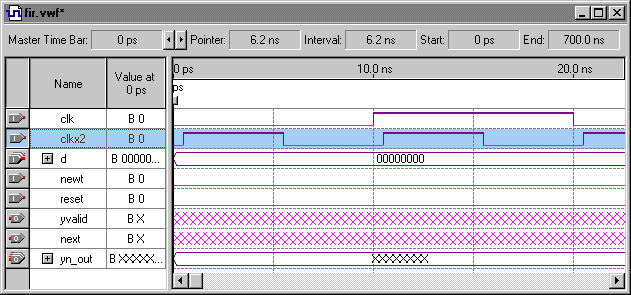
Choose Value > Clock (Edit menu). The Clock dialog box appears.
Under Base waveform on, select Clock settings and select clockb in the list.
Click OK. The clkx2 waveform is created according to the clockb clock settings.
![]()
|
To edit the d input bus waveform, follow these steps:
To select the entire d input bus waveform, click the Selection and Smart Drawing Tool on the waveform's handle. The entire bus, including the waveform, is highlighted.
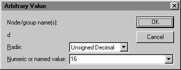
Choose Value > Arbitrary Value (Edit menu). The Arbitrary Value dialog box appears.
In the Radix list, select Unsigned Decimal.
In the Numeric or named value list, type 16.
![]()
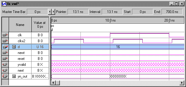
Click OK. When a message asks if you want to change the radix of the other nodes in the d input bus waveform, click Yes. The d input bus waveform is displayed with an unsigned decimal value of 16.
![]()
|
To edit the newt input node waveform, follow these steps:
To select the entire newt input node waveform, click the Selection and Smart Drawing Tool on the waveform's handle. The entire waveform is highlighted.
Choose Value > Clock (Edit menu). The Clock dialog box appears.
Under Base waveform on, select Time period.
Type 80 in the Period box, and select ns in the list.
In the Duty Cycle list, type or select 25.
Click OK. The waveform displays a repeating waveform with a period of 80 ns and a duty cycle of 25% on the newt input signal.
![]()
|
To edit the reset input node waveform, follow these steps:
Click the Selection and Smart Drawing Tool at time 0 ns on the reset input waveform and drag the pointer to time 20 ns.
Right-click the selected interval and choose Value > Forcing Low (right button pop-up menu).
![]()
Click the Selection and Smart Drawing Tool at time 20 ns on the reset input waveform and drag the pointer to time 40 ns.
Right-click the selected interval and choose Value > Forcing High (right button pop-up menu).
To see the entire waveform, choose Fit in Window (View menu).
Click the Selection and Smart Drawing Tool at time 40 ns on the reset input waveform and drag the pointer to the end of the stimulus file.
Right-click the selected interval and choose Value > Forcing Low (right button pop-up menu).
![]()
To save the file, choose Save (File menu).
|
The Quartus II software allows you to simulate an entire design, or to simulate any part of a design. You can designate any design entity in a project as the "simulation focus," which is the design entity you want to simulate.
The Simulator settings allow you to specify the simulation focus, the type of simulation that should be performed, the time period covered by the simulation, the source of vector stimuli, and other options.
You can create and save your own customized groups of settings for use with the Quartus II Simulator, or you can use the settings that are generated automatically each time you create a new project.
| The procedures in this session explain how to view and edit Simulator settings using menu commands and dialog boxes. However, you can also easily specify all Simulator settings by following the steps in the Simulator Settings Wizard (Assignments menu). |
|
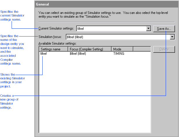
The General Simulator settings page allows you to select an existing group of Simulator settings, define and save a new group of Simulator settings, specify the simulation focus, and delete existing settings.
To view the default Simulator general settings created for the current project, follow these steps:
Choose Settings (Assignments menu). The Settings dialog box appears.
In the Category list, select General under Simulator Settings. The General page appears. The General page displays the default Simulator settings created by the Quartus II software when you created the project.
![]()
|
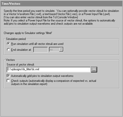
The Time/Vectors Simulator settings page allows you to specify the time period covered by the simulation and the source of vector stimuli. You can specify a VWF, VEC File, Vector Table Output File (.tbl) or Power Input File (.pwf) as the source of vector stimuli. Alternatively, you can enter vector stimuli directly in the Tcl Console window.
To specify the simulation time period and the source of vector stimuli, follow these steps:
In the Settings dialog box, select Time/Vectors under Simulator Settings. The Time/Vectors page appears.
Under Simulation period, make sure Run simulation until all vector stimuli are used is selected.
Under Vectors, in the Source of vector stimuli box, type D:\qdesigns\fir_filter\fir.vwf, or click Browse (...) to select the file.
| When you run a simulation, the Simulator automatically searches for a vector source file (.vwf, .vec, or .tbl) with the same name as the current Simulator settings. Therefore, it is not necessary to explicitly specify a vector source file if the vector source file has the same name as the current Simulator settings. |
Under Vectors, make sure Automatically add pins to simulation output waveforms is turned on.
![]()
|
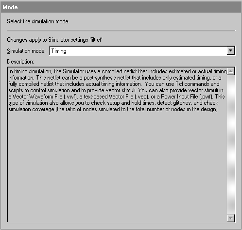
The Mode Simulator settings page allows you to specify which type of simulation should be performed. Two types of simulation are available: functional simulation and timing simulation. Functional simulation tests the logical operation of the design by simulating the behavior of flattened netlists extracted from the design files. Timing simulation uses a fully compiled netlist, which includes actual timing information, to test the logical and timing performance of the design.
To specify the timing simulation mode, follow these steps:
In the Settings dialog box, select Mode under Simulator Settings. The Mode page appears.
In the Simulation mode list, make sure Timing is selected. A description of timing simulation appears in the Description field.
![]()
|
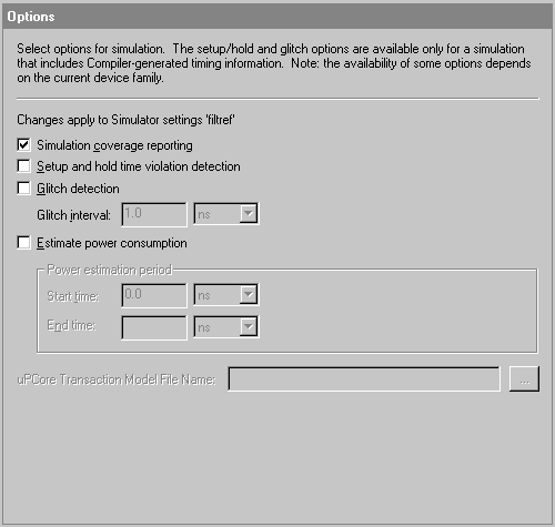
The Options Simulator settings page allows you to specify options for monitoring design conditions during simulation.
To monitor the simulation coverage, follow these steps:
In the Settings dialog box, select Options under Simulator Settings. The Options page appears.
Make sure Simulation coverage reporting is turned on.
![]()
Click OK. All of the settings and options you specified are saved as the filtref Simulator settings. When you run the Simulator, these Simulator settings control simulation processing.
|
To run the simulation, follow these steps:
Choose Run Simulation (Processing menu).
The Simulator immediately begins to simulate the filtref top-level design entity and all of its subordinate design entities, using the filtref Simulator settings and the fir.vwf vector source file. As the Simulator processes the input vectors and simulates the design, the Status window automatically displays, as a percentage, the total simulation progress and the time spent in each stage of the simulation.
The results of the simulation are updated in the Simulation Report window. The Simulator runs in the background, freeing your computer—and other portions of the Quartus II software—for other work. However, the simulation of this design entity is short and you should not have to wait long for it to finish.
If you receive a message indicating that simulation was successful and there are no errors or warnings displayed in the Messages window, click OK to close the message box.
| You should correct any errors or warnings in your design or VWF and resimulate it until it is error-free before proceeding with the tutorial. If the Simulator displays any error or warning messages in the Messages window, select the message and choose Locate (right button pop-up menu) to find its source(s), and/or choose Help (right button pop-up menu) to display help on the message. |
| You can go to "Creating a Breakpoint" in Quartus II Help for more information about breakpoints. You can go to "Updating Embedded Memory" in Quartus II Help for more information about updating embedded memory. | |
|
During simulation, the Simulation Report window appears automatically. The Simulation Report displays useful information about the current simulation. By default, the Simulation Waveforms section appears in the Simulation Report window. The Simulation Waveforms section shows the behavior of the specified outputs during simulation.
The Simulation Report also contains other useful sections that provide information about the current simulation, including information about the Simulator settings, simulation messages, and simulation processing times.
|
Now that you have simulated the logic levels of the focus entity, the output node waveforms are defined. You can view and analyze the output logic levels in the Simulation Waveforms section.
To view the Simulation Waveforms section:
If necessary, in the left pane of the Simulation Report window, select Simulation Waveforms. The Simulation Waveforms section appears in the right pane of the Report window.
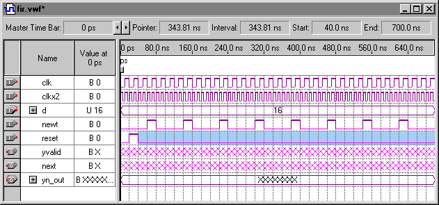
To see the entire waveform, choose Fit in Window (View menu).
![]()
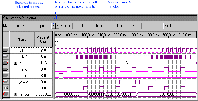
The Waveform Editor allows you to manipulate the data in the following ways:
You can change the radix used to display group values by selecting a group, choosing Properties (right button pop-up menu), and selecting a new radix in the Radix list.
You can move the Master Time Bar right and left to successive transitions by clicking the movement arrows. You can also drag the Master Time Bar by its handle.
You can zoom in and out with the Zoom Tool button ![]() on the toolbar, and with the Zoom In, Zoom Out, Fit in Window, and Zoom commands (View menu).
on the toolbar, and with the Zoom In, Zoom Out, Fit in Window, and Zoom commands (View menu).
You can create additional time bars and use them to measure distances between transitions.
|
To create a time bar, follow these steps:
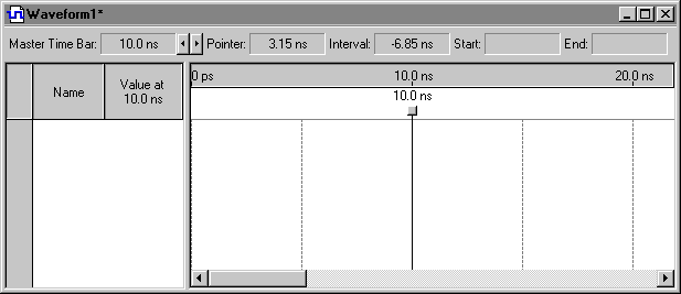
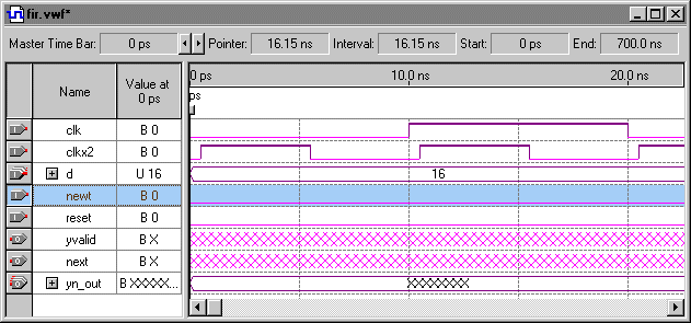
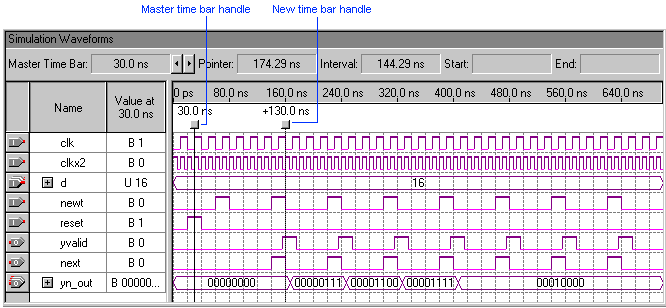
With the Selection and Smart Drawing Tool, click the Master Time Bar handle and drag it until the time bar is aligned with the second rising edge of the clk signal. At the top of the window, the Master Time Bar box displays 30.0 ns.
Move the Selection and Smart Drawing Tool pointer in the waveform to the time of 160 ns. At the top of the window, the Pointer box displays 160.0 ns, the time where the pointer is located. Note that the Interval box displays 130.0 ns, the time difference between the Master Time Bar and the Selection and Smart Drawing Tool location.
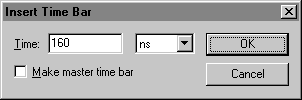
Right-click in the waveform drawing area and choose Insert Time Bar (right button pop-up menu). The Insert Time Bar dialog box appears.
In the Time box, type 160 and select ns in the list.
![]()
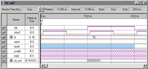
Click OK. A new time bar appears on the waveform at 160.0 ns. The text +130.0 ns is shown above the second time bar, indicating the time difference from the new time bar to the Master Time Bar.
![]()
| You can move a time bar by dragging its handle to the desired point in the waveform. All measurement data is updated accordingly. |
|